The Silicon Chip Theremin Build

I have fancied building a theremin for years but, until recently, never quite got determined enough. Then, quite independantly,
a friend asked if I could make one for him. This was the excuse I needed and set about figuring out how best to go about this task.
Events conspired against me time-wise and I ended up opting for the 'soft option' of using a kit, I managed to find a kit put together by Jaycar of a Silicon Chip magazine design that was well documented
and looked reasonable - the only problem being availability, it is a discontinued line.
I found one on EBay and set about looking for a better case.
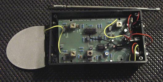 1- The SC Theremin 1- The SC Theremin
As the guy I was building it for had spent a couple of years working with me to
update an industrial control system from obsolete DEC computers running Unix and Ultrix to a more maintainable, mostly M$Windows based system, I figured there must
be a case in the 'scrap' piles I could use - I decided on a SCSI tape backup drive, an ideal memento of the project!
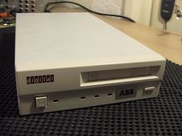 2- The DEC TapeDrive 2- The DEC TapeDrive
This case contains a switched-mode power supply, giving +5v and +12v, the theremin kit already has a 6v regulator on the PCB, so it will
happily run from 12v. The only problem with this supply is that it runs from front to back of the case, denying me one side for aerial
mounting unless I put the aerials at the front of the case where the volume aerial will have to be rather close to the mains switch.
Other options considered were to have one aerial on the front panel (which is plastic) and one on the rear - leaving little room for
controls; or to put both sockets on the underside
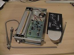
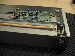 3- Test fitting 3- Test fitting
I wanted the aerials to be removable to make storage easier so sockets would be required. PL259 chassis sockets have a 4 bolt mounting
flange, ideal for the thin steel case I'm working with. Plugs designed for URM67 co-axial cable have an internal thread of 7/16ths UNC,
this just happens to be a reasonable (if slightly odd) thread to cut on 10mm stainless tell tube using a die nut.


In order to get a decent distance between the aerials I thought I would make them with screened 'extender' sections, this would allow the
aerials to be about 18 inches apart and make their fixing into the PL239 plugs so much easier.
A short length of 10mm stainless steel tube with a 1mm wall thickness would allow 6mm tube to thread through it with a 1mm radial clearance
thus effectively creating a rigid co-axial cable. By binding the 6mm tube with PTFE thread tape I can guarantee its concentricity without
compromising insulation. A small amount of epoxy resin secures and seals both ends. A 0.75mm (20AWG) stranded wire easily pushes into the
4mm bore of the 6mm tube, soldering to stainless isn't feasable so I stripped a good amount (maybe 18 inches), folded this bare section
back on itself and, having the still sleeved end of this wire sticking out where the socket would be, pulled the stripped wire into the tube
and rammed it tight, giving a connection as good as any crimped terminal. The plug could then be screwed onto the 10mm tube and the wire
soldered to the plug's centre pin.
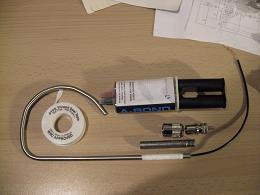 4- Aerial construction 4- Aerial construction
So having all the key bits its time to try it out and see if a metal box is OK (have you noticed how theremins are always in wooden or
plastic boxes?) and find out if the aerial construction results in too high a capacitance to earth.
 5- Old and New 5- Old and New
NOTE: In the above picture you can see the aerial sockets are wired with cheap hook-up wire and the only control is the standard volume pot,
floating on short flying wires, also I am still using the supplied tiny loudspeaker.
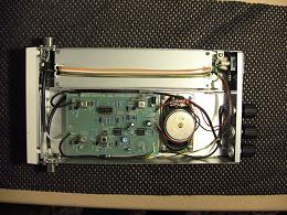 6- Final Wiring 6- Final Wiring
Final wiring complete, co-axial wire for aerial sockets, a better loudspeaker and volume and seperate 'zero' pots for volume and pitch
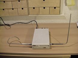 7- Testing 7- Testing
Cover refitted and time for a final check, all works well - better than expected for the aerials' experimental construction!
The screened section of both aerials are totally blind to hand movement and the exposed sections are far enough apart to
prevent cross-interference in use.
A second set of aerials could easily be made with new shapes and rapid interchanging is easy.
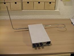 8- Rear View 8- Rear View
Here you can see the rear panel's layout of 'Pitch zero', 'Audio Volume', 'Volume zero' and power socket.
I will get some sort of audio and/or video demo in due course, as usual with theremins, building is the easy bit!
|
|
Navigation
Max Baars excellent article on modifying the SC theremin
Celia Sheen and her Theremin on BBC Radio3
|

 1- The SC Theremin
 2- The DEC TapeDrive
 3- Test fitting
 4- Aerial construction
 5- Old and New
 6- Final Wiring
 7- Testing
 8- Rear View