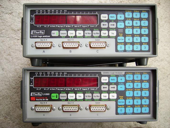
The Thurlby LA 160 Logic Analyser - Notes and Tips

If you are new to the LA160, you need to be careful when you connect it to any circuitry. It only accepts 5v logic signals (-0.5v to +5.5v MAX), anything else needs go through a 'data pod' to level shift it (more about data pods later).
* These supplies are NOT protected for over-current or back-feeding!
Do not short-circuit or connect to external power sources
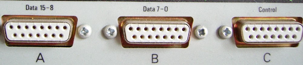
In the above diagram, the first column is pin number, then data port A and B bit number, then finally, the Control port pin allocation where :-
TE3 = Trigger Enable 3
TE2 = Trigger Enable 2
TE1 = Trigger Enable 1
TE0 = Trigger Enable 0
Arm = Trigger Arm
CE1 = Clock Enable 1
CE0 = Clock Enable 0
Clock = Clock Input
Input Characteristics:-
The 24 inputs have the following characteristics:
Data inputs:
1*LSTTL Schmitt trigger gate load
typical positive going threshold = +1.7v
typical negative going threshold = +0.9v
Trigger Enable inputs:
1*LSTTL standard gate load
threshold = +1.4v
Clock input, Clock Enable inputs and Trigger Arm input:
1* F series standard gate load
typical threshold =+1.5v
Typical input current for all inputs is:
logic 'High' input = +20uA
logic 'Low' input = -400uA
Note: unconnected inputs will float high.
Main ROM version -
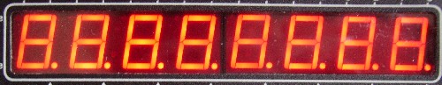
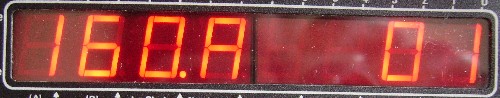
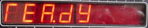
When you switch on, the display will quickly sequence through two states before settling on 'READY'.
First it will do a display check, all segments lit,
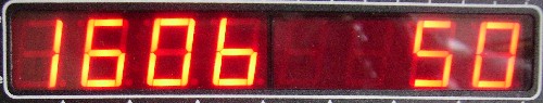
then it shows the digits '160', speed ('A' or 'b') and EPROM version.
Currently I have talked to owners of version 01, 32, 33 and 50 ROMs, all copied and archived --- I would love to know if your ROM version is
different, I believe there are still more versions out there!
Main ROM Bugs -
The only bugs I am aware of at the minute are that both the v32 and v33 ROMs fail to respond to a trigger word under some conditions, this may or may not bother you, I have only once been in a position to want the facility and soon found an alternate way of triggering the analyser.
I have no experience of the v01 ROMs. There are two variants of this ROM, depending on the hardware - the other ROMs all allow for both hardware speeds via a setting stored in RAM.
Start-up sequence
EPROMs
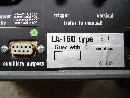
Labels on rear panel
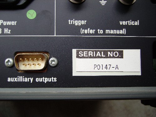
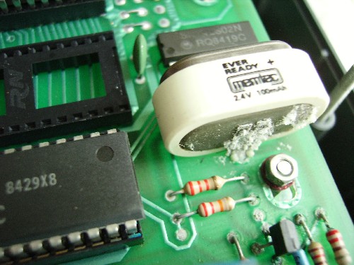
If you turn it on and it asks "SET TYPE" the internal ni-cad battery is flat, probably best to remove it before it leaks and wrecks the PCB.
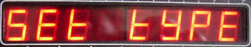
A sticker on the back should identify "LA160 A" or "LA160 B", answer the above question with the letter "A" or "B", this sets the internal dividers to match the hardware counters (actually any key but ‘B’ will set the LA160 to ‘A’, so be careful to press ‘B’ if that is what you have!).
If you set your 160 to the wrong type (see rear label), it should still work OK, a mismatch of hardware and entered 'type' will just cause analysis timing to be wrong. It is possible to reset the LA160 by holding the ESCAPE button for
5 seconds or so (you will see it count down on the display), if the NiCad battery has enough charge to maintain the tiny CMOS RAM, the LA160 will show it's start-up message of type and ROM version. If the NiCad is flat, the LA160 will again ask "SET TYPE", giving you the chance to re-enter the correct type (A or B).
If you need to change the type code but the LA160 doesn't ask the question, you will have to either put the analyser away until the battery is again flat or open the unit up and disconnect the battery (requiring desoldering – do NOT short it out!).
LR64 “Extended Facilities” ROM -
This enables the front panel commands that are in brackets, a few are (for me) useful - see owners manual, towards back.
The manual that comes with the LA-PC software states that the main ROM should be "LA-160-xx where xx is 50 or above" and the LR64 ROM should be "LR64-PC-xx where xx is 50 or above". This suggests there could be a ROM version 51 or higher.
Pods -
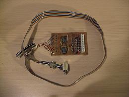
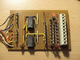
There were two types of pod, one was a simple buffer affair, the other had variable sensitivity. I have seen one LA160 with a set of three pods being auctioned on the internet, it went for far more than I could justify! Attached are images of the basic type of pod, the diagram includes two sets of legends on the right side, this depends on if you use it for data or trigger channels, to the left is the D-connector pin numbers to the LA160.
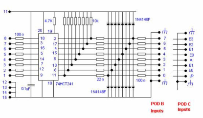
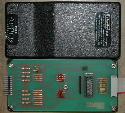
I cobbled together a version of this WITH the protection diodes shown in the diagram, as I couldn't find the octal 74HCT241 I built mine with two 74ABT125N CMOS quad buffers. I used it on my son's car fuel injectors and then unplugged the pod from the LA160 while still connected to the car - I killed the buffer chips! (luckily socketed).
A 5v6 zener was added across the pod's power rails during the repair - no more problems :-)
The Display -
I think the biggest weakness of the LA160 is its 7segment display, what it does manage to show on this is brilliant –but- you could have an extra option for that, thanks to the LR64 ROM.
Viewer Program -
There was a viewer program called LA-PC, it was supplied on a single floppy disk and ran as a DOS exe.
To use that software, the LR-64 extended facilities ROM was required, being supplied as a kit, along with a new main ROM, version 50 "or higher". I managed to get a copy to try but found it would not run under Windows ME unless booted in true DOS mode, a DOS shell being useless.
I had already written a M$VisualBasic program that allows the LA160 to download a data capture to a pc and show it as a timing diagram (multi-channel oscilloscope-style), so the LA-PC software was deemed 'too difficult' and filed away.
My version of the viewer program, LA-Prog, allows captured data to be saved and studied at your leisure rather than lost on power-down! The LA-160's internal NiCad battery only supplies the tiny settings RAM, not the data capture RAM.
To use the program, you will need to download the zipped exe file (
LA-PROG_exe zip)
and make an RS232 lead as per the diagram in the owner's manual (NON-STANDARD! details below).
EPROM Failure -
The mechanism for EPROMs going wrong is that there's a charge on the gate (or not) of a FET which is put there when the device is programmed. This eventually leaks away. It is also affected by static charges, UV light of the correct wavelength etc.
An EPROM's programming does have a finite lifetime before bits start changing state, and these EPROMs are from the 1980’s. It would be safest to erase it and re-program it if you have the equipment. At least now there is an archived copy of a few ROM versions!
WANTED :-
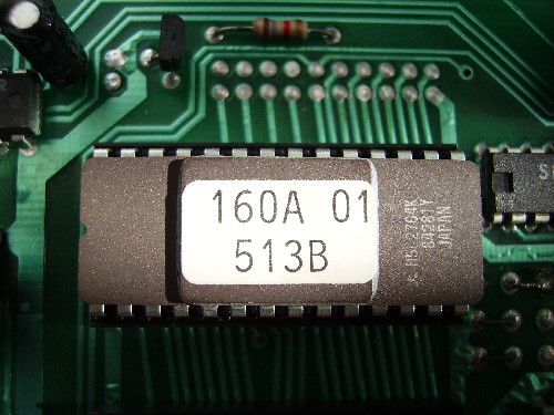
I have the following versions of main ROM copied,
- 160A 01 - specific to 10MHz hardware
- 160B 01 - specific to 20MHz hardware
- 160 32
- 160 33
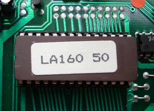
- 160 50
If you have anything other than these, or any other LA160- related information, I would be delighted to hear from you!
LINKS :-
Jump to the site Downloads page »
Return to the LA160 main page »
Return to the site Home page »
List of contributors
The following people have provided information used during the compilation of and/or checking of this write-up.
Hopefully complete,but contact me if I have used some of your data and not listed you or you wish to be removed from this list or have your contributions edited out.
- Tad Filip
- Andrew Holme
- Lee Davison
- Terry G. Tipper
- Henk v Doren
- Steve (slassembly)
- Joe McElvenney
The above names are in no particular order :-)
You can contact me at :- 
|
