The JH String Filter Project

Jürgen Haible designed a string filter in 2004, he then redesigned it in 2008 using a different filter topology in order
to produce and sell a PCB for it.
Jürgen's webpage » gives the full story

NOTE! I freely mix Imperial and metric dimensions in this project, matrix board is still produced with 0.1" spacing
despite some listings stating a metric approximation, and faders are produced with 40mm or 60mm (etc.) travels.
When I first saw this project I decided it would be ideal for my set-up, one of my all-time favourite sounds is an orchestra's string section when they produce that lush top end in a mix.
Jürgen Haible announced the PCBs being available and I went for it. To save time and effort (or because I'm lazy) I also opted for Tobias Schilly's parts kit (TS-Parts in Berlin), all the PCB mounting bits in a single box.
I wanted to make this project work for its money so it made sense to make all 40 filter outputs available independently and have 40 faders giving any mix I desired.
The original design had four toggle switches to select the four 'partials', each composed of ten equi-spaced filter outputs, to the stereo output; either that partial was enabled or disabled - I figured it would be no more work to use centre-off switches to allow the option for each partial to go to left output, off, or right output.
It seems I have a specification (of sorts) for the front panel.
A scrounge around the workshop produced a second-hand 19 inch, 3U case that looked ideal (a sort of datalogger by a company called Durag, also from Germany!). Some maths showed that each fader had to be 0.4 inch or less in order to fit and could have a maximum of 60mm travel. Such a fader was located and 40 were ordered; meanwhile I produced a dimensioned drawing of the front panel.
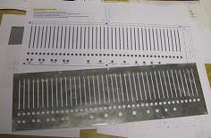
1- The front panel arrives from lazer-cutting
I opted for lazer-cutting as the 40 fader slots needed to be reasonably accurate for the project to look neat, it would have taken me days to attempt this with any other technique.

2- A close-up of the cutting spatter
This is my first experience with lazer-cutting, I was curious to see how clean the edges would be. I consider the pot shaft
holes and socket mounting holes to be OK, just needing deburring, but the slider shaft slots were far too rough as they stay visible on the finshed panel. I deburred them with a flat needle file and emery cloth in order to cause less 'snagging' on the slider shafts.
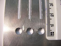
3- A close-up of the cutting spatter

4- Fader PCB mounting detail
The case front rails had a slot along their full length, a sort of inverted keyhole shape. This was used at the ends to attach them to the end panels with setscrews. As this only occupied the first half-inch or so, the rest of the slot was vacant. I got this milled out to 1.6mm which allowed the matrix board to push snugly in. By using the top and bottom rails the matrix board is securely held.

5- Fader PCB mounting detail
The matrix board was just wide enough to hold 8 faders so five pieces of matrix board are required, one with the left-hand edge left on, three with both left and right edges removed and one with just the right-hand edge left on. All had the copper tracks running from top to bottom.

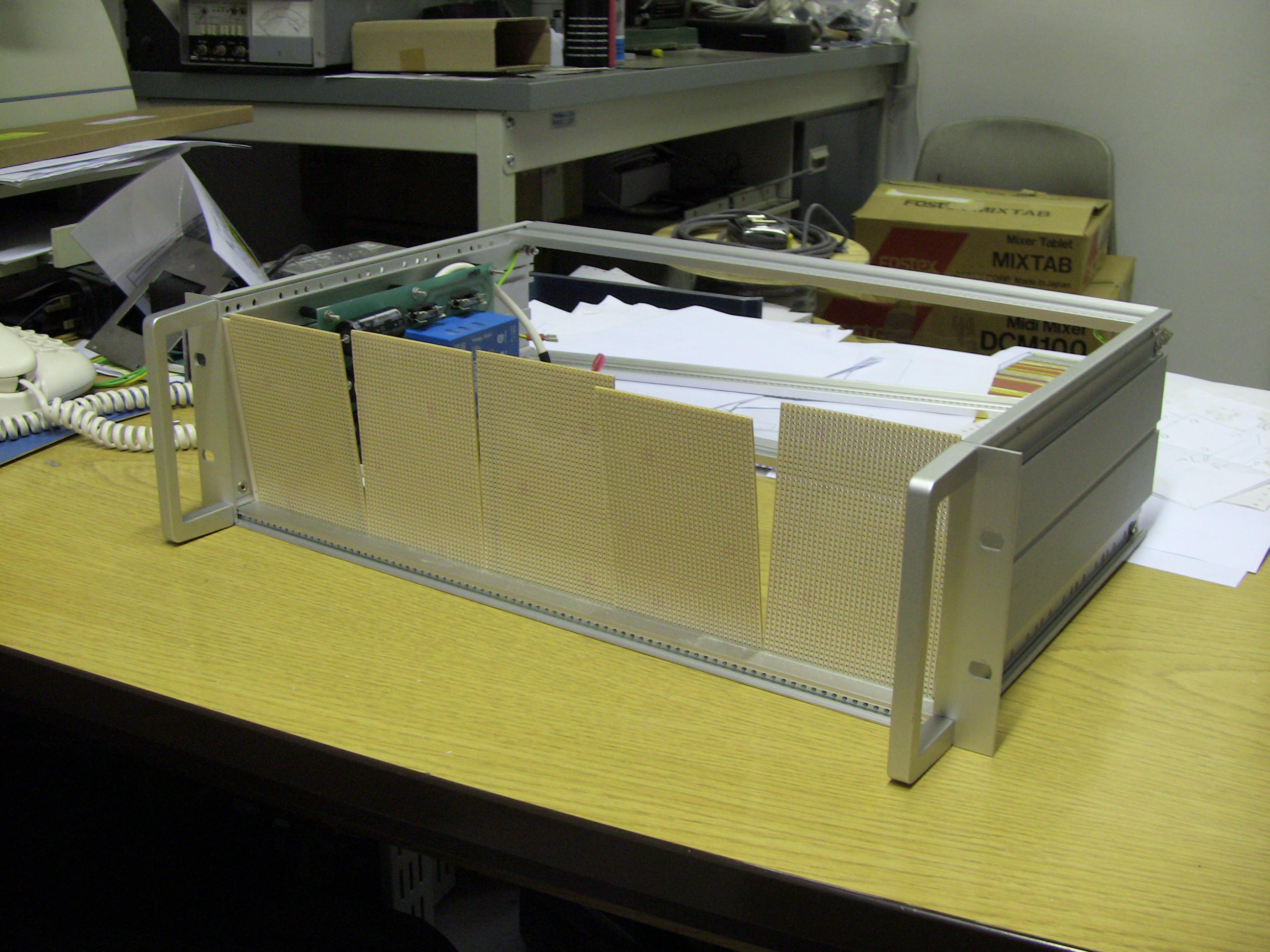
6- The fader bank modules assembled
All five boards butt up to produce a single surface of 0.1 inch matrix holes.

7- The front panel submodules
3.5mm sockets and toggle switches mounted directly to the front panel.
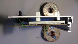
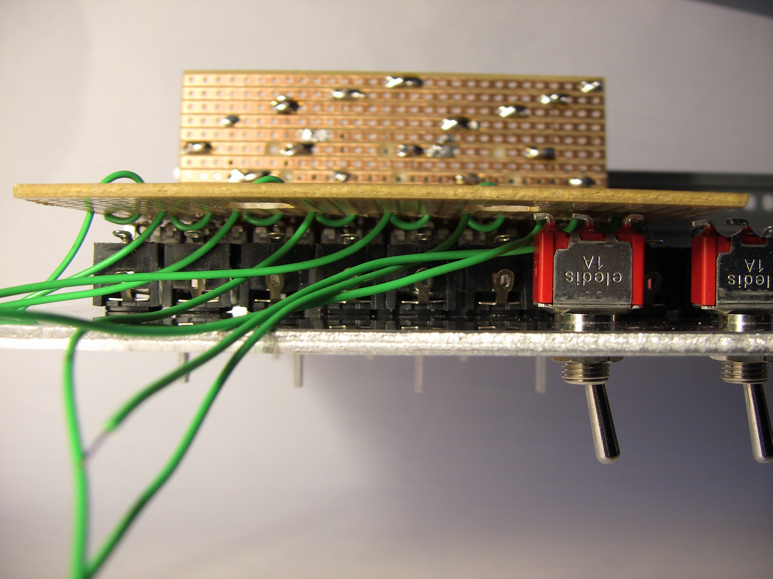
8- End cross-section of front panel assembly
With the matrix boards in place there is no access to the sockets for wiring so I opted for a flying wire from the matrix board threading through an enlarged hole such that the wire could be soldered to the socket and then the surplus pulled back as the matrix board was eased into place.
This also shows the 'distribution rail' matrix board on the back of the faders, copper tracks running across all eight faders and resistors jumping as required between the two.

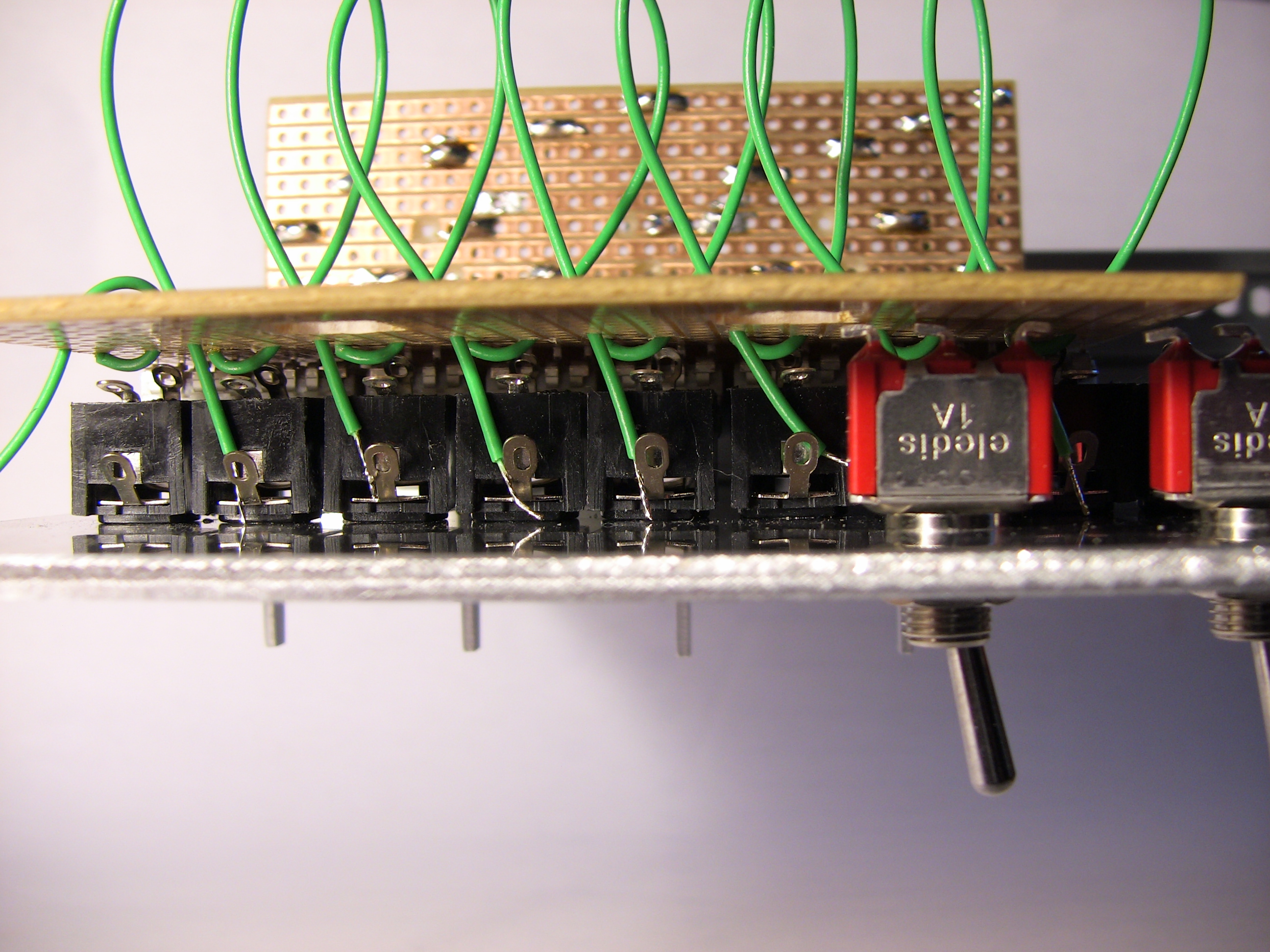
9- Bottom cross-section of front panel assembly
Another view of the 'distribution rail' and the rather tight space for the toggle switches.
All the flying wires pulled through for soldering.

10- Socket wiring detail
The flying wires pulled back as they would be after soldering.
You can just see holes in the matrix board ready for fitting the pots, leaving just the shafts protruding through the front panel.
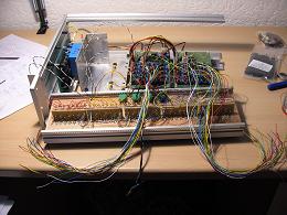
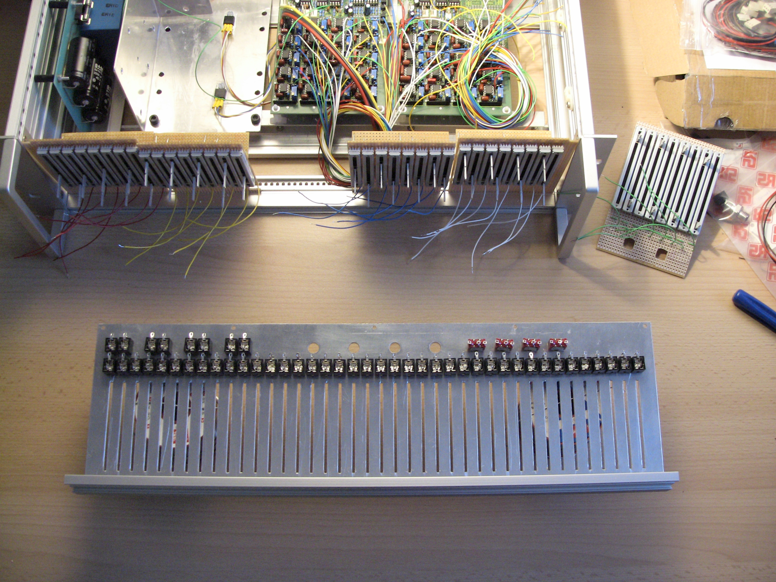
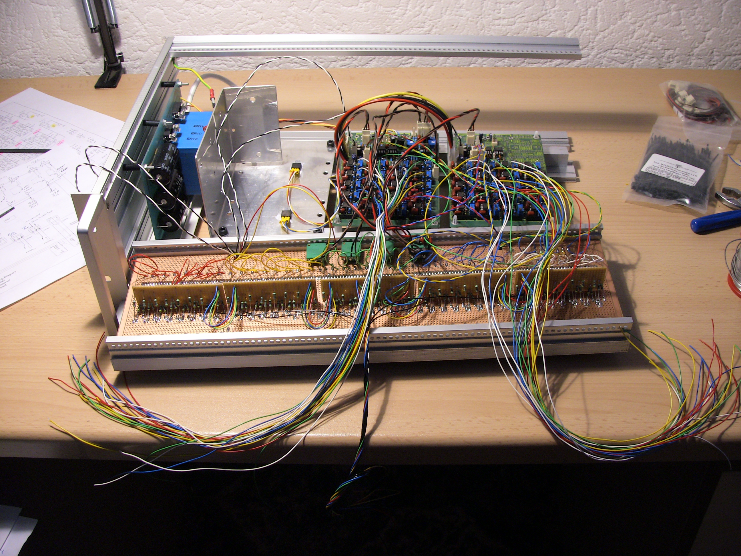
11- PCB to front panel wiring
All five fader assemblies fitted to the front panel, all five distribution rails connected together to produce a common earth for all 40 faders and four output busses, echoing the original 'partial' groupings of the JH design. Long tails have been soldered to the switches and input and output sockets, ready to connect to the chassis, and all forty filter outputs are prepared ready to connect to the distribution rails.
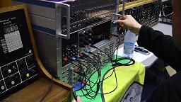
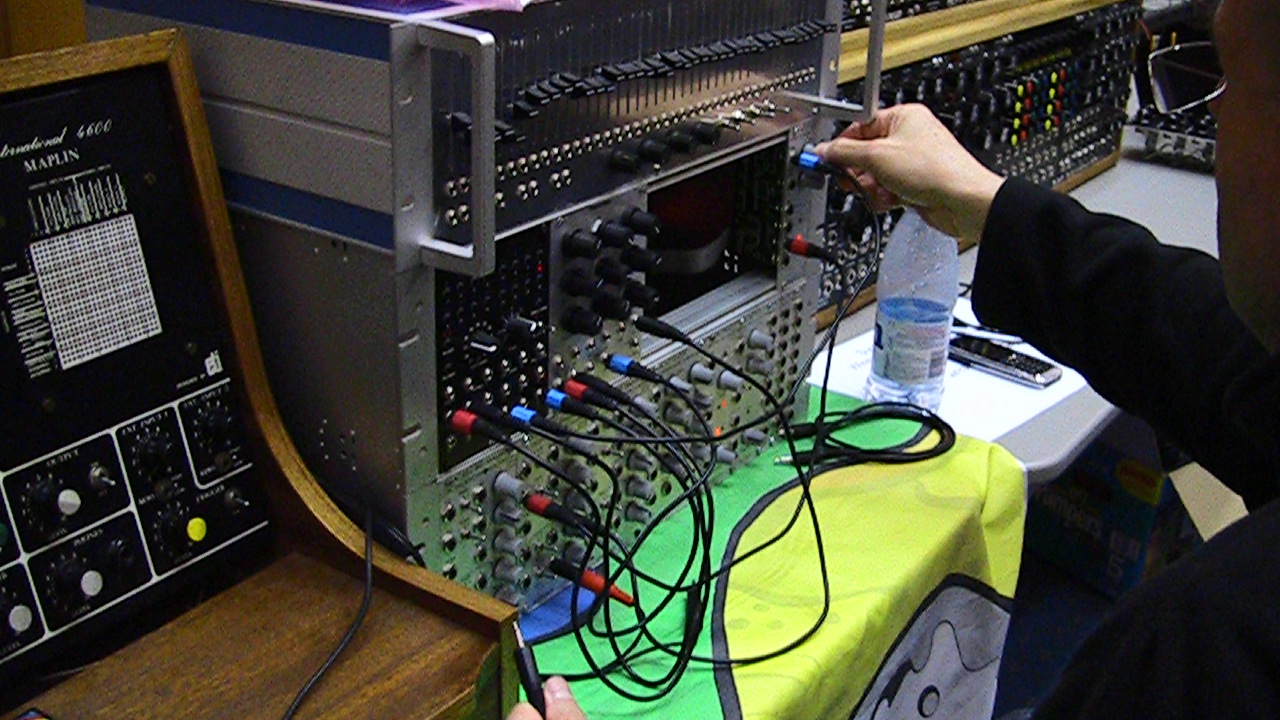
Synth DIY 2009
I took the almost finished string filter to the Cambridge Synth DIY meeting but couldn't demo it due to a couple of unresolved bugs.
|
|
Navigation
Jürgen's original webpage closed after his untimely death but is now relocated. It describes the string filter »
Scott Juskiw describes a mod similar to mine »
My FFT analysis data of the filter »
|